Gnomish Engineer
Still working on the Poultryizer...
Sunday, October 31, 2010
Encoder DRO Madness
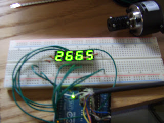
I bought 4 digit, 7 segment LED displays from sparkfun, along with two shiny new Ardunio Unos.
What you're seeing here is one of each, all wired up and ready to play with.
It took a little while to get the display working properly, because there are so many pins to control, and so few to control them with.
All of the segments are run in parallel (for example, the top horizontal segment on each of the four digits is connected together, like wise for the upper-right/vertical segments for each of the four digits, and so on). But each digit has it's own power pin, so essentially what you have to do is write your letter/number, turn the first digit on, turn the first digit off, write the second letter/number, turn the second digit on, turn the second digit off, etc... and do it very fast.
This worked great, except it was too fast :P all of my digits blurred on all of the segments. So I added a 100 ms delay after each on, but before the off. This was a bit too slow, the digits were now displayed properly, but flashing serially. I trimmed the delay to 10 ms and everything was honkey dorey.
Well, displaying a static number was kinda neat and all, but relatively useless. So, I pulled out my ol'e encoder and dusted it off. Either through coincidence or through destiny there were exactly two pins open on the digital side of the Arduino, the exact amount needed to make the encoder work (per a previous post).
(towards the top of my working surface you're also seeing a flex sensor I got from spark fun too... however that's for another lame post - it seems that it needs an op-amp to work properly, and that's now on it's way in the mail).
It was a matter of merging the encoder and the 4 segment display codes, and like magicks, it worked (sorta).
The code is highly highly highly bloated, but it works... better than the Serial.Println() encoder version... which proves to me that the serial out was what was dragging the original encoder code down. There's a lot more work to do to get this thing in useable condition - right now it only displays positive counts (playing with the math should fix that), I'm not using a decimal currently (it seems it might actually get a little complicated compared to straight digits), and my encoder count is off (again, I think it's just in the math).
With some simple eye-ball testing, it seems to not be skipping any counts at roughly 60 rpm (1 turn in one sec). But it's noticeably off when I really twirl it fast. Not sure if it's due to the bloated code (about 375 lines in the Arduino!) or if it's the delay()'s. I'll keep playing and trim down the code greatly before I take out the delays (because I'm not sure how to separate the digits without them!).
But that's for another time, I've got to play Fable 3 now.
Wednesday, August 4, 2010
Encoders make the world go around
For the CNC project, I'm planning to use stepper motors as they're much much much much much cheaper than their servo brethren. But the down side to this is that they're they dumbest of the two.
Basically in a servo the control says to the servo "go to 180 degrees" and the servo goes to 180, and stays there, it actually has a built in rotary encoder to see if it starts to stray to 179.999 or 180.001. If it does, it corrects itself and maintains 180 until the control tells it to go somewhere else.
The Stepper is aptly named because when the control says to the stepper "go to 180 degrees", the stepper will step a certain number of increments until it thinks it's at 180 degrees - for example a common step angle is 1.8 degrees per step.
180/1.8 = 100 steps - so the motor will blindly make 100 steps and hold itself there.
In a perfect world, this isn't a problem. But in the real world anything can happen. If the stepper makes it's 100 steps, the control will assume it's at 180 degrees. Now, if the motor gets bumped, it's possible that it could have shifted a step(or two). Now in the real world the motor is at 181.8 degrees, but the control still thinks it's at 180. This is a huge problem if you're concerned with accurate positioning... such as in a CNC machine.
So, I was hoping to take some inexpensive digital calipers and hack them into a linear encoder. The machine would then be as accurate as the calipers that I hacked. But I tore apart some cheap $8 calipers from Harbor Freight, only to find pretty much nothing inside. I was stumped. They were nothing like my dial calipers - no mini-rack and pinion or anything that a mechanical minded person could comprehend. It was pretty much the sliding portion, the portion it slides on, a tiny circuit board and a battery - there wasn't even any visible means of connection between the two (as in - how did it make measurements from it's relative movement?). I later found out, after tons of digging that the stationary portion (long part) has specifically spaced magnets (or magnetized bits) in it, while the sliding part (short part with the readout) has a hall-effect sensor type thingy in it to read the spacings and know where it is based on that.
Short of it is, I couldn't use it because I couldn't find anything to hack and read a signal from.
So after putting that on the back burner for a while, I stumbled upon a (relatively) inexpensive rotary encoder, with surprising resolution.
I even got the cute coupling to go with it.
Below you can see my quick setup (the beer is actually incredibly important).
I wanted to play with it, so I hooked it up to my Arduino for a clean 5V power, and used my DMM to read each wire as I fiddled with the shaft (giggidy).
So far, from playing and the operation manual (barely that... more like operation page), I found that basically there are 6 signal wires. A/A- ; B/B- and Z/Z-. A and B are signals, Z is the 'reference'. Z is supposed to switch (go from 0 to about 3.4V or vice-versa) with 1 revolution. I got a 1000 resolution encoder, so A and B both pulse 1000 times for each revolution (that's 0.36 degrees of resolution, for those counting. not too shabby for $86). I found that reading voltage across A and A- gives readings bouncing back and forth from -3.4 and 3.4 (nothing in between), while reading between A and GND bounces between 3.4 and 0. B/B- and Z/Z- act similarly. I'll have to dink more, but the plan is to use the Arduino and it's interrupt routines to decode the encoder. Pair that with my stepper, and I might actually have something here...
UPDATE =D
I've been tinkering with the encoder, and still can't figure a good use for the A-, B- and Z- (I guess I'm not using it right). I've been told by an Electrical dude that in the real world Z is only used for homing (or Zeroing).
I deduced a beautiful way to make A+ and B+ work for me. It seems I can figure direction just from those two signal pulses.
Short of it is, I got it working!
Had a few problems initally. The first and most newbish being 'unsigned' int - I couldn't figure why when I decremented, my number shot from 0 to 65535, instead of -1 like I was expecting (I knew it 'cycled back around' I just didn't know why the negative numbers where omitted). Took me a good 30 minutes to figure I needed to take off 'unsigned'.
I originally had "Serial.println(position)" after every pulse, and that pretty much limited me to oh, maybe 3 rpm or I'd start noticing skipped pulses (or worse, it'd skip just right to where it'd read what it thought was a decrement signal when it was incrementing). Spent quite a while before I realized just how slow the Serial.println was slowing the entire thing down. I changed up my program to delay for one second then print. Without an accurate rotary table to measure it, I can't say for sure, but it seemed like that fixed it. My set up should (in theory) be accurate to roughly 0.25 degrees. I'd be willing to bet that's not too far off just from crude testing.
Fun stuff.
H-bridge part 2 - First Blood
I finally got the H-bridge soldered together:
There weren't really any directions to speak of, just the circuit diagram. The silkscreen for the board was incomplete, so it was a bit of a challenge, since I'm an electronics newb. I was second guessing myself quite a bit. I actually ended up confirming a couple of component placements by the pictures. Not sure if it works yet... infact I'm still trying to confirm the inputs and outputs. But it's soldered, and I claim victory, so far.
Friday, July 23, 2010
Lawnmowbot - the H-bridge or homemade PCB...
I've decided to make the R/C lawnmower straight out of Makezine's (vol 22) pages. I figured I had most of the parts, and my dad could probably use it (he's got a lot of grass to mow).
It was coming along nicely, until I hit the H-bridge. I've always wanted to make an H-bridge, and this was the perfect opportunity. Step 1 is to fabricate your own PCB, which is ubercool. I tried the method described in the magazine, only to realize that it doesn't work with inkjet printers - only laser printers. I was skeptical to begin with, but I tried anyway with my inkjet, and lo and behold, the transfer never transfered! I later discovered that the toner in laser printers is something of a polymer type powder, and the laser melts it onto the paper - so you're really getting something more or less like plastic ink with a laser printer. The transfer method works with this because you simply re-melt it onto your copper board.
But I was not to be deterred! I used a liberal sharpie marker and free handed the pattern to the board, then etched. It worked! Sorta. When I went to drill the holes, I realized this was a dumb idea, as I didn't have the spacing even close. So that was junk (but still, good experience).
I also learned that PCB drill bits break if you even look at them wrong. Sadly, I only bought three of them and broke 'em all (the first one not even lasting two holes). Lesson learned here - USE A DRILL PRESS!
Yesterday I finally broke down and bought a laser printer (yay cheap crap agian!).
The printer was $60 (with a 1000 page toner cartridge included)... replacement toner cartridges are $70... go figure. To go along with my $60 printer, I bought a stack of $20 glossy paper for it.
Set up and printing was a breeze (Ubuntu is the best ever).
The copper cladded board was cleaned with a scouring pad and then acetone. Get all the oxidation off. After you do, be careful not to touch it with your fingers and get your oils on it.
(So shiny!)
I taped the PCB print, face down to the board and used an iron to transfer the image.
I pressed the iron on very hard for about thirty seconds, then used the tip (that's what she said) and pressed all over the board. (Key theme here being lots of pressure). Check out this video on instructables. If nothing else it has good music (admit it, you were chairdancing).
The newly ironed PCB is soaked in some soapy water. The idea here is that the paper that originally held the toner gets soggy enough that you can easily remove it without damaging the print. After several tries here, I discovered that I wasn't using enough pressure with the iron, so it required a few re-dos.
You can see here the post-paper-peeling. The dark spot towards the lower left is where the print pulled up with the paper (I didn't press hard enough there!). I repaired it with a thick layer of sharpie marker.
Warning: FUN PART AHEAD!
What you're seeing here is muriactic Acid and Hydrogen Peroxide. Pretty menacing looking, I know. Muriactic Acid is used to etch concrete, and is pretty nasty stuff (it smoked a little when I first poured it in my dish). So take precautions here. I used gloves and eye protection. I found it at the hardware store, in the paint department.
(Incidentally, what you're also seeing here is the main spindle chucked up in my minilathe for the CNC project, its only about 60% finished - but that's for another post!)
Find a good dish (I used a Pyrex pie dish) and mix in 2 parts Hydrogen Peroxide / 1 part muriactic acid, enough to fully immerse your board. Using a wooden or plastic stirring utensil, mix it all up and dunk in your board. I swirled the mixture over the board continuously - you could also use a bubbler (like the kind used in your average aquarium) to agitate the mixture. You'll soon begin to see the mixture turning green (that's copper) and eventually, the unprinted parts of the circuit board will completely erode away, leaving only the fiberglass beneath.
The before and after of it all:
Finally, the Finished Product. The sharpie repair held up good enough. Next step is to drill and tin it, Then solder in the junk. But that'll have to wait, as I broke all my drill bits.
My advice, buy by the dozen.
Tuesday, June 29, 2010
CNC Machine Tool - Prelude
I've been toying with my own CNC machine for nearly as long as I've been an engineer. It's evolved over years and years. I've scanned many of the homebrew CNCs out there, but none were to my liking. Wood has no place in a machine tool. Neither does a Dremel. If you're going to spend so much time and money, do it right. So for the better part of the past decade I've been mulling my own machine tool in my head, sketching ideas, refining them, throwing them out and starting over. It really came down to balancing three things:
1) Money. This thing can't cost me too much. If the price starts to soar, it'd be more economical (and much quicker) to just buy one.2) Abilities/Tools. I could design a column cast of iron, machined to incredible tolerances. But it'd do me no good, as I can't make it. I have to design around things I can do and tools I have (or can easily get).
3) Capabilities. I'm not going to waste my time on a tool that can only machine a pebble sized part. Or one that can only cut to meter tolerances.
Many considerations came into play (and still are bouncing back and forth). First was the configuration. There are dozens and dozens of configurations for machine tools, but what satisfies all three of my stipulations best? I soon learned it was the gantry mill (and soon after I learned that, I discovered that there were sub-configurations I had to figure on). Anyway... A gantry mill is a simple structure that can be built with simple hand tools and simple materials. So far, very few special components had to be found.
Behold! The Gantry Mill!
Well, a partial concept anyway. Simple materials make up the bulk. Square and rectangular tubing make for a great start. Linear guides and ballscrews (bought from ebay. Thankyou cheap Chinese crap!) add great precision and capability. Servomotors would be nice, but don't even look at pricing those, you'll just get depressed. Steppers are an affordable option (and have a few hidden benefits) that provide the control needed. Down the road I plan to play with open-loop feedback (perhaps from a few hacked digital calipers?) for even better accuracy and control.
More to come on the Gantry Mill, The Spindle is currently under construction, and is actually the largest hurdle to production. But, like I said, more on that later...
Subscribe to:
Posts (Atom)